Categories:
- Product Name:
- Ceiling Mounting Antenna
- Item no:
- VTMIMO-617-6000-2
- views:
- Loading...
 |
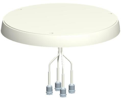
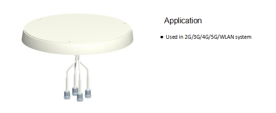
MIMO Omnidirectional Ceiling Antenna
Part Number:VTMIMO-617-6000-2
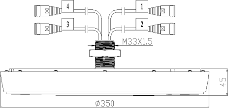
1. Dimension(Unit:mm)
2.Installation Sketch
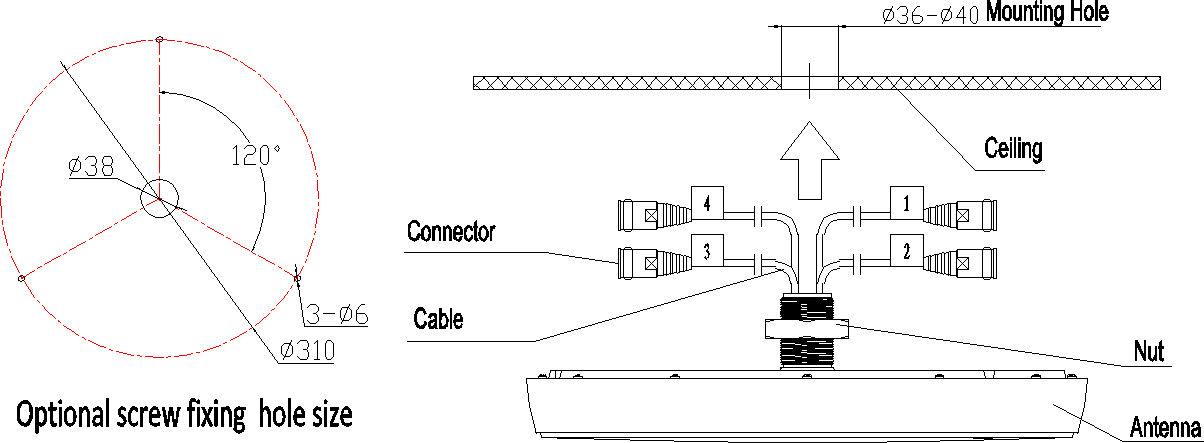
1、Drill a round hole Φ36mm~Φ40mm on the ceiling.
2、Match the antenna to the round hole.
3、Fix the antenna onto the ceiling with the screws.
Attention!
The hole on the ceiling must be slightly bigger than the antenna connector flange, and the
base plate should be in close contact with the ceiling, which influences the performance
of the antenna.
3.Electrical Characteristics
|
No. |
Item |
Specifications |
|||
|
1 |
Frequency Range-MHz |
617-960 |
1710~2700 |
3300~3800 |
4900-6000 |
|
2 |
Polarization |
4*Linear |
|||
|
3 |
Maximum Gain (dBi) |
4 |
5 |
6 |
6 |
|
4 |
Horizontal beam width (°) |
360 |
|||
|
5 |
Vertical beam width (°)(Typical values) |
80 |
50 |
40 |
50 |
|
6 |
Isolation (dB) |
≥16 |
≥20 |
≥25 |
≥25 |
|
7 |
VSWR |
≤2.0 |
≤1.8 |
||
|
8 |
Impedance-Ω |
50 |
|||
|
9 |
Maximum power (W) |
50 |
|||
|
10 |
Grounding |
DC Ground |
|||
4. Mechanical Characteristics
No.
Item
Specification
1
Connector
4*4.3-10 Female or 4* N-Female
2
Connector position
Bottom
3
Exposed cable size (cm)
30(or customer requirement)
4
Height/width/depth (mm)
Φ350*45
5
Packing size (mm)
410*140*420
6
Weight (kg)
1.3
7
Radome material
ABS
8
Radome color
White
9
Operating temperature (℃)
-40~60
10
Application
Indoor
11
Mounting
Nut
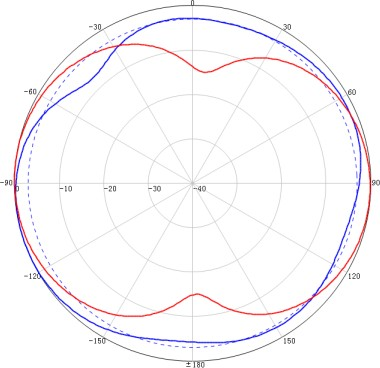
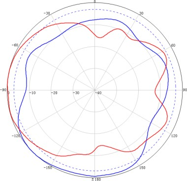
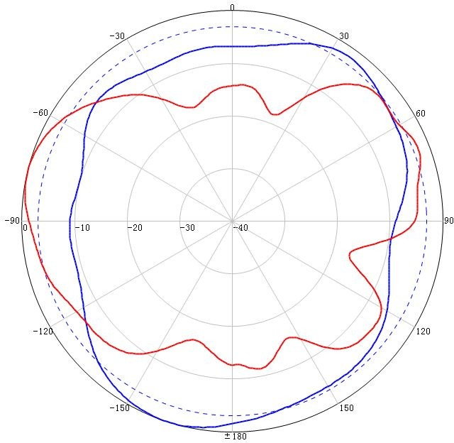
617~960MHz Typical pattern: 1710~2700MHz Typical pattern: 3300~6000MHz Typical pattern:
